Light Switch Diagram: Circuits for Planning Electrical Paths
A light switch diagram helps you plan the paths electrical current will take in your room.
A light switch diagram is a type of circuit diagram. Circuit diagrams are like blueprints that illustrate the flow of electricity through a circuit of electronic components such as wires, switches, power sources, and lighting fixtures. The focus of these diagrams is to show how these elements are connected together. Each component in the diagram is represented by a symbol. There are standard symbols that are used to represent typical electrical features in circuit diagrams, such as switches or batteries.
Circuit diagrams are an essential tool of any profession dealing with electricity, including electricians, engineers and scientists. However, many light switch diagrams are drawn with do-it-yourself renovators in mind, rather than professional electricians. For this reason, the electrical components are often shown as simplified pictures of the actual objects, rather than the more abstract symbols that are standard among professionals.

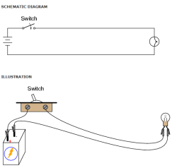
A simple light switch diagram. Image Source: Learning Electronics.
It is important to note that in these diagrams, the layout of the components in real space does not correspond with their position on the diagram. Rather, they are drawn in the simplest possible configuration in order to make it as easy as possible to understand how the circuit works. For example, all connections are shown clearly and all wires are drawn as straight lines. This can be confusing for those who aren’t professional electricians.
A helpful hint is to concentrate on understanding the connections between the components, and not get caught up in the physical shape of the whole circuit in the diagram. Drawings that depict the position of lighting fixtures in an actual space are called lighting plans, and these do not usually show the wiring of the fixtures.
How do I read a light switch diagram?
Light switch diagrams are useful for building circuits involving light switches, and understanding how they work. In order to understand them better, we are going to take a look at a basic lighting circuit and its corresponding diagram. The most basic diagrams are for simple circuits involving one switch that turns one light on or off. This type of switch is commonly called a single pole single throw (SPST) switch. Current flows through a switch to the load, in this case, a light fixture. When you flip the switch off, the circuit is broken, the flow of electricity is interrupted, and the light turns off. A light switch has two terminals and sometimes a ground terminal.

Although light switch diagrams may seem confusing at first, with a little practice they become easy to understand.
The hot wire (the wire which carries the electric potential) from the power source is connected to one of the terminals. The hot wire going to the light fixture is connected to the second terminal. Hot wires are usually coded black in light switch diagrams as well as in actual wiring (in fact the color coding of wiring is nationally standardized). The wire that conducts the power back to the power source is called the neutral wire, and is usually coded white.
In reality, the hot and neutral wires are bundled together along with a ground wire into a single cable. The ground wire must be properly grounded into your lighting box. The ground wire is sometimes shown in light switch diagrams as well, however it is sometimes omitted in simpler diagrams.
How can a light switch diagram help me with my home lighting design?
Light switch diagrams are useful for anyone who would like to understand how electrical circuits work. They are especially useful for understanding how to replace broken switches, or replace existing switches with different types (ie. adding dimmers or three-way switches).
Some of the most common problems that are shown in light switch diagrams include:
- How to wire a basic switch. These are useful to follow if you have a broken switch that needs replacing. If you have a switch that seems loose or wobbly, or alternately, stiff or difficult to switch, than your switch may need replacing. If your lights flicker, it could be a sign that your switch is shorting. If the switch is completely broken then your light will not turn on at all, or in rare cases, it will not turn off at all.
- How to install three-way (or four- or more- way) switches. A three-way switch is the name given to a circuit where a single light is controlled by switches in two separate locations. Yes, it is confusing that it is called a “three-way” switch, however, for reasons unknown, this is the traditional name for this type of arrangement. Three-way switch arrangements commonly used for stairways (one switch is at the top, and the other at the bottom), rooms with multiple doorways (a switch at each doorway), and for garage lights(one switch in the garage, and another to turn on the garage light from inside the house).
- Adding specialty switches. By this I mean any type of switch that is not simply a lever you turn on and off. One common alternative is a dimmer switch. Others include switches that are operated with keys, timers, motion sensors or photoelectric eyes that sense daylight. Some switches are connected with outlets (a combination switch). There are also switches available that allow you to alternate between a low-level safety light source, such as a night light, and a bright light that will illuminate a room.
What are the safety concerns when using light switch diagrams to re-wire a light switch?
It is always best to consult an electrician before attempting any electrical work yourself. Faulty wiring will cause the components to overheat and start a fire. Below are some of the most common dangers in electrical wiring.
Short Circuits

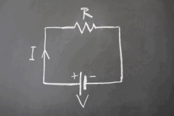
A simple circuit diagram.
An electric current will always follow the easiest path that is available. If the wires of a circuit are not insulated (most wires are covered in rubber or another material that electric current cannot pass through) and touch each other, the current will pass from one to the other and back to the power source without going through the light fixture. This is a shorter and easier path for the current – hence the name “short circuit”. Short circuits allow stronger-than-usual flow of electricity through the wires, causing them to overheat, creating a fire hazard.
Compatibility of Components
In addition to making sure the wires themselves are properly arranged, you need to make sure that any components of your circuit are compatible with the others. For example, fluorescent and neon lights as well as loads greater than 1,000 watts require different types of dimmers than incandescent lights. Any switches should match the amp and voltage ratings for the circuit, and if your home has aluminum wiring (most homes have copper wiring, the switches should be designated CU-AL for compatibility. Light switch diagrams usually do not indicate these potential issues – another reason why it is a good idea to have an electrician check your wiring before attempting any repairs.
Putting it all together:
Light switch diagrams are a useful tool to help understand how the electrical wiring works in your home.
- They give you a scheme for how to configure a circuit to meet various lighting needs, including dimmers and three-way switches.
- Be safe! Before you attempt any home wiring, consult with an electrician. Faulty wiring is very dangerous, as it can cause wires to overheat and start a fire.
This article was written exclusively for Home Lighting Tips by Katherine Bader, M.A. Mrs. Bader studied art history and architecture before leaving the professional world to raise her children.